22 December 2010

Slab with drop and column head

Welcome back to Revit-IT! I am sure everyone is looking forward for the coming Season's holiday.
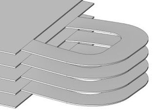
As usual, today's article is about a model I encountered in our office. It's about a slab with drop panel and column head. One of my co-workers modeled this structure using "model in-place". No doubt, using this method had some issues. One of the issues I noticed is that the column head and the drop panel is not an integrated part of the column. So when the floor level height change, you have to move every column head and shortened the column which is really a tedious job to do.

You are better off when you build this structure using a structural column family. With this method, you are more flexible instead of modeling in place. You can reuse the family in other project thereby your office will be more efficient. It took me some hours to develop these two family types for this project. Moral lesson here, as a Cad Manager you must have an overview what your modelers are doing and not allow them to just having their way with modeling.
Merry Christmas to everyone and wishing you all the very best for the coming New Year 2011.

12 December 2010

Profiles in Revit

In Revit, a profile is a single line, chain of connected lines, or closed loop that can be used to generate a form. Profiles can be designed so that the user can manipulate it to change the geometry of a form. It can be added to the following forms types namely, extrusions, lofts and sweeps.
The following is an example wherein a predefined profile is used in slab edge.
The profile shape for this particular slab edge is a flexible one. The user can duplicate the predefined family properties or select from a list of predefined types.

Other common use of profiles can be found in Wall reveals and sweeps, steel framing which I usually advocate the use of it for complex framing form.
Thanks for dropping by and if you have any questions, just feel free to contact me.

25 November 2010

How to set the default location for Revit® 2011 help documentation

Let me share this tip to you to wrap-up this last full week of November. Remember, it's Thanksgiving Day today.

It is often annoying if you are using a PC without an Internet connection and you would like to consult the Help documentation. The following is a solution from Autodesk.

Add the following 3 lines to the bottom of the Revit.ini file:

[Documentation]
UseHelpServer=1
HelpBrowser=0

To specify online help documentation use UseHelpServer=1
To specify local help documentation use UseHelpServer=0


To read more about it, follow the link:
http://usa.autodesk.com/adsk/servlet/ps/dl/item?siteID=123112&id=14994272&linkID=9243099

12 November 2010

More about curved ramps

Here’s a little tip about curved ramps.
I’ve been discussing with my co-worker that one can create a curved ramp even though the width varies and even with an irregular form. The trick here is to do the basic modeling of the curved ramp using a constant width say for example 5000 mm. Important to know is that the Run you sketch along the path of the ramp is the average centerline of the model. After you adjust all the properties of the ramp and you are satisfied with the initial modeling, you can go ahead with using Modify: Ramps>Edit Sketch. You can now edit the form of the ramp (outside bounds), presto … a new curved ramp with an irregular shape.


Feel free to contact me if you have any problems about creating a curved ramp. Of course, any suggestion is always welcome. Happy curved ramp modeling.

9 November 2010

Curved Ramps in Revit

How to create a curved ramp in Revit
This question was asked today during my hectic hours in our office by a co-worker. It seems this might be difficult as one may think. After regrouping my memory during my way back home, a light goes on in my mind. Forget about my colleague suggestion, keep an open mind as you do in the past and do not use the sub element point tool in floors as he was planning to do so.
For this case, you do not have to think of creating a mass nor using the sub element point to reflect the level it was to go up. Very simple, you just create the curved ramps with Revit Ramp tool itself. It is there, just look at the Revit Help if you do not know how to use it. Take a good look at the options, because to create curved ramps are there. The easiest way to add a ramp is to sketch a run. However, the Run tool limits the design of your ramp to straight runs, straight runs with landings, and spiral ramps. You need some guide lines to do the job.

Tip: The default settings for the Top Level and Top Offset properties may make the ramp too long. Try setting the Top Level to the current level, and the Top Offset to a lower value.

4 November 2010

Rotate a single plan view in Revit

Rotate a single plan view in Revit

Presentation of a rotated plan on a sheet can sometimes be a headache for a novice user who does not know how to handle this situation. In Revit you can either choose your project orientation as “True North” or “Project North”. In the example below, we want to present the South West Wing of the plan horizontally on a sheet. This can be a dangerous procedure if you do not know what you are doing because rotating a view will have an impact on the entire orientation of the structure which I suppose you do not intend to do so.

To accomplish this rotated single plan view, do the following:

1. Duplicate the view with detailing.
2. Go to the view just duplicated.
3. Open the Element Properties and change the Orientation to “Project North”.
4. Turn all the Crop Regions.
5. Choose MODIFY and select the crop region.
6. Use the ROTATE command to turn the crop region, which will turn the view in the opposite direction.
7. Place the rotated plan view on your sheet.

15 October 2010

Slanted Walls – Leaning Walls

Slanted Walls – Leaning Walls

Revit cannot lean out a wall. You can hear and read many discussions about it, but still it has not been fully explained. You can use a curtain wall surface or formed from using mass. But in my opinion it is cryptic, difficult and cumbersome. I would rather advise Revit users to use a structural beam family. It is easy to model it from one floor level to another level using a reference plane. You can use cut geometry to remove the unwanted areas.


Hopefully that someday, Autodesk will listen to us to add this leaning wall tool, with an opening tool in it, 'cause adding windows or doors to it is such a pain.
I have suggested this item to AUGI Revit Structure Wish List and I am just keeping my fingers crossed that it will take an attention in the next voting round.

1 October 2010

Revit Structure Wish List Ballot Results, August 2010

Glad to see that my wish list for Revit Structure landed as third place during the August 2010 voting.
To see the results follow this link: http://www.augi.com/revit/results3.asp

20 September 2010

Detach from Central File – Confusing issue?

Detach from Central File – Confusing issue?

I usually get a question about this issue: Detach from Central (DFC).
Thru this blog, I will try to clarify what DFC really means.
Many Revit users ask himself, why I cannot detach the model from the Central file. It is an option during opening a Revit project file.

Every time one tried to detach the model from the central file and save it, it some how reverts itself back to a central file. If you read and fully understand the Revit manual, DFC will only Open Workshared Files Independent of the Central File. This allows anybody to open and use the file, as well as do a save as without destroying the original Central File. You just break the relationship with the original central file. If you save, it will be a “save-as”, and the file will be a new central file in the saved location.

The following is an excerpt from the Revit Manual:

After you open the file, it no longer has any path or permissions information. It is in a state similar to when worksharing was first enabled; all elements in the file can be modified, but no changes can be saved back to the central file. If you save the file, it is saved as a new central file.

Note: If a longer-lasting independent copy of the central file is needed, such as when the central file is suspected to be corrupt, detach from the central file and save it as a new central file. Note that existing local files cannot synchronize with this new central file and new local files created from the detached central file cannot synchronize with the old central file.

If a non-workshared file is opened with Detach from Central selected, Revit Structure ignores the option, and opens the file normally.

Summing up: You can never convert it back to a single-user file, if that’s what’s in your mind.

15 August 2010

AutoCAD Details in your library to go into Revit

AutoCAD Details in your library to go into Revit

In Revit, there is a possibility to present a construction detail of the project either using the live views generated from the building model or drawing a new detail from scratch using the Drafting View. If you have in mind to reuse a detail, (i.e. a standard detail) I would recommend that you use the Drafting View in Revit. You can export it to an external file for reuse some other time.

If you have developed “standard” details over the years in your office in AutoCAD format, I would suggest that you make use of it. This strategy is a hybrid approach in detailing within Revit. It is saving on overhead and the unnecessary modeling effort.

Below are the general steps to follow if you want to keep your detail as an AutoCAD DWG file:

1. Go to Insert Tab > Import panel > Import Line Weights and select your Conversion TXT file for importing. If you see all number 1’s here on the right hand column of the table, it means that you do not have a correct file setting loaded.


2. Click on the LOAD button to select your office standard file if any, otherwise you will need to make one and do a save as for the settings just made. Note that this is based on the Color of AutoCAD layers. It will be used in converting DWG files when imported or Linked. Configure the table below, the way Revit Structure should apply lineweights to the imported elements.


3. Link the AutoCAD DWG file (thus – Do Not Import!). Linking acts as an Xref and if there is a change in the external file, it will be automatically updated.
4. Place the detail under Drafting View in the Project Browser. This can be referenced on a sheet.


Alternatively, you can convert an AutoCAD detail into Revit entities. This method is my recommendation to you and I believe it is a better approach in the long run. There is less overhead and will not mess at all your Revit file. You can use Detail Components and Filled Regions thereby making a Project detail a true Revit 2D Detail. The graphical representation of the detail produced will be conformed to your Revit Standards.

Below is an outline of the conversion process.

1. Open a NEW Project and save as a Dummy file that you can discard or save for later conversions.
2. In the same Revit session, open your Project file or a clean Detail Project file.
3. Switch Windows to your Dummy file and create a new Drafting View for the detail to be imported, View Tab > Drafting View > [New Drafting View (Name Detail/Scale – OK)].
4. Make sure that the DWG you are importing has no errors, (i.e. wayward AEC blocks, unused blocks, etc.). It is best to open the DWG file and clean them up in their original environment first. Purge and audit file before importing to avoid some headaches later.
5. Import the DWG file into the Drafting View just created, Insert Tab > Import Panel > Import CAD.
6. Click on the DWG just inserted to explode it, Import Instance Panel > Explode > Full Explode. You cannot explode a linked file or an imported symbol that would yield more than 10.000 entities.
7. Ignore the warnings that you might get and press Delete Elements if any.
8. Delete all Dimensions, Leaders, Hatch regions and other entities that you feel are no longer the style in your Revit Standard. The text will be converted into Revit Text which you can select and change its Type to suit your Revit Text Style. Add a Leader in text if desired. Use your custom Revit “Break Line” which is a Detail Component.
9. Start editing other entities. Select one layer at a time and convert it into the proper Revit Line style using the Type Selector drop down in the Properties dialog box.
10. If you are finish with editing, select all of the detail entities and copy into clipboard by pressing Ctrl-C.
11. Switch Windows to a new Drafting View in your Project or Detail Project file and Paste the detail by pressing Ctrl-V. With this procedure you avoid having all the AutoCAD DWG layers, line type, filled region, etc from messing your project file.

With a tedious conversion process depicted above, I can understand that some companies will be reluctant to go through this method. However, this can be an opportunity to review your Standard Detail Library and make sure that the detail representation is up-to-date with the current local building regulations. For later investigation, you can create intelligent 2D details that can be scheduled and connected to the 3D model. If your budget is tight, why not let a trainee do the job as well. This will give them a head start in understanding the detailing of construction element.

My last words to you are, give this conversion method a try and maximize the future benefits for your business. Form a team to do the job, a team with motivation, fearless open-mindedness and then the reward of success in implementing Revit detailing in your organization is within your reach. Revit Structure technology is gaining speed and your company cannot afford to let this technology passes by.

11 August 2010

Revit Printing to Pdf's

Revit Printing to Pdf's

We have gone to using DWF for Revit output via "Export DWF", and if PDF is required, we print out of the DWF file. So far, DWF has given us much smaller, quicker files than PDF.

However, there was an incident in our office wherein the users cannot produce a PDF directly from the Revit program nor out of a DWF file. The problem was due to a custom font file, an extended Arial font. Some of the characters in this extended font file are interfering during the creation of a PDF print.

We received the following errors, an excerpt:

%%[ ProductName: Distiller ]%%
%%[ Error: typecheck; OffendingCommand: put ]%%
Stack:
500
/FEB
26
[/.notdef /b /e /s /t /a /n /d /space /c /o /r /u /i /p /f /l /m
/equal /two /five /zero /g /k /v /one /.notdef /.notdef /.notdef
/.notdef /.notdef /.notdef /.notdef /.notdef /.notdef /.notdef
...
/.notdef /.notdef /.notdef /.notdef /.notdef /.notdef /.notdef
/.notdef /.notdef /.notdef]
/FEB


%%[ Flushing: rest of job (to end-of-file) will be ignored ]%%
%%[ Warning: PostScript error. No PDF file produced. ] %%

I have tried more than 3 PDF printers and all of them gave the same error, FeB 500 symbol will not print. The only PDF printer that will work is doPDF version 7, developed by Softland that could be found in the web.
I would like to thank the maker of this wonderful PDF print program. This saved us a lot of man hours.

5 July 2010

Sheets in a Linked Revit file

The following is one of my discussions in Revit forum and I want to share it with you. I will be updating it if ever additional response is available. The subject matter is an important item for consultants like us.

Sheets in a Linked Revit file


I linked a Revit file into my own project. I can only view all the plan views of the linked file. Is there a way to view the sheets of the linked file? I tried to set the visibility of the linked file to custom but still cannot find a way to view the sheets contain in the linked file.

If this is not possible, maybe this can be an item for a wish list for the next version?
Hear from some experts out there and thanks in advance for your time.


Responses to my inquiry:
---

This is not possible and I am not sure if it ever will be possible. The main reason being that your doing double work by trying to get your sheets set up in your 2 seperate projects when you could have just done it in 1 of them.
__________________
BIMHighway
Content management and cost estimating solution for Revit


---

I disagree I see this more as being able to link consultants drawings in with your own, to create a full set of documentation, as long as it was quick and easy I have no issue with this and would be nice.
__________________
AJS
Digital Project Co-ordinator


---

We are multi-discipline and each discipline has its own Revit file per project. It would be very helpfull if all files could be linked together in a master and all discipline sheets could be plotted from the master file. This would allow any project team member the ability to plot or view any sheet from any discipline without having to open multiple files.

---

Then I would recommend that you make 1 file that links in all the departments files into, that you will create all the sheets and views for printing. Then you would be able to view any discipline and any could print. Just remember that you can have all your annotations inside the individual files and have them come through in the master file.
__________________
BIMHighway
Content management and cost estimating solution for Revit

---

The issue with creating one master file for the entire project's sheets, is that we end up with 20 people sharing one file to get the project completed. With multiple users accessing the central file through their local files, we have experienced many crashes and lockouts when the amount of users go over 5-6.

1 July 2010

Modelling Complex Surfaces

A good reference material that I use in Modelling Complex Surfaces and Structures Using the New Modelling Tools for Autodesk Revit 2010 is the one presented by Marcello Sgambelluri – John A. Martin & Associates in AU2009,code SE9114-1 last year 2009 in November.

The course teaches you how to accurately model complex geometry using the new modelling tools in the concept modelling portion of Revit 2010.

It is a very good reference material. Give it a shot.

2 June 2010

Revit workset, a common problem

Suppose you receive a Revit file from another consultant that was a part of a “workset” and it was saved without relinquishing back to the “Central file”, this will cause you some problems.
First of all, you will be locked out to save the file as a new file. You might see a message saying that the file was created by another user and therefore it will not certainly allow you to edit the file because you are a different user.

How can you get around this problem and save the file to a new one?

Here are some suggestions that I advice my friends using Revit.

- Open the file as a “Detach from Central”.
- Save it using the option “Make it a New Central file”.
- Look at the user name that has locked it and then copy the file to a new local name.
- Meanwhile, change your Revit User name to that of the individual who locked the file.
- Open the newer copy and Save to Central followed by “Relinquish all”.
- Change back your Revit User Name to your original one.

Take note that when you use “Detach from Central” and the Save the file, it is going to be a New Central File.

26 May 2010

Revit Local File is corrupt

Today one of my office mate was in panic. The tension in his body was apparent.
His local file got corrupted and he do not know what to do. I was asked together with my other mate to see his problem.

In our office, a quick reference guide about Revit Structure is present. But this guy did not bother to have a look what to do if the local file will not sync with the Central file. Instead of getting nervy which will not help you out of your tense feeling, he is beter off taking a glimp of the FAQ. I told him, if the local file will not sync with the Central File, make a new local file with another name. He was glad that the new local works smoothly and you can see his smile in his face.

A rule of thumb here is: "A local file a day keeps the support away".